4 Good class design to build the application right
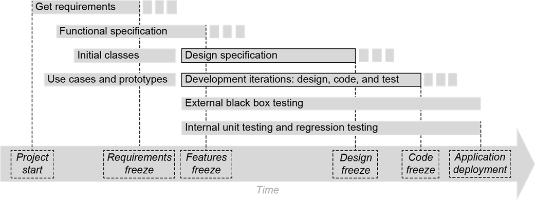
This chapter positions design as a disciplined, iterative activity that spans most of the development lifecycle, complementing requirements, prototyping, and implementation. Initial classes emerge from the requirements, then evolve through development iterations, with external black-box testing and internal testing proceeding in parallel. Project milestones (such as requirements and feature freeze) guide progress but may shift; the overarching aim is to ensure we build the application right through thoughtful design and continuous verification.
Good class design centers on two goals: cohesion and loose coupling. Cohesion is achieved by giving each class a single, primary responsibility (as illustrated by separating operational, maintenance, and cleaning concerns of an automobile into distinct classes), which limits reasons for change. Loose coupling follows the Principle of Least Knowledge: classes depend on others through minimal, well-defined interfaces, reducing ripple effects from change. The chapter shows how UML class diagrams document classes and their relationships at varying levels of detail, covering dependency (including transient dependencies), aggregation versus composition (and multiplicity), and generalization via inheritance. It also explains how abstract classes and interfaces define required behaviors, enforce contracts on subclasses, and guide extension points.
To capture runtime behavior, the chapter introduces UML state diagrams for modeling how an object’s state evolves in response to events, and UML sequence diagrams for mapping object interactions across a use case—both helping validate that responsibilities and relationships are correctly assigned. All design artifacts (class, state, and sequence diagrams) belong in a design specification aimed at current and future developers, often accompanied by an Internal Test Plan. Unit and regression tests verify that the application is implemented correctly and remains stable across iterations, while the design specification is frozen at a milestone yet updated prudently as the system evolves.
Creating an application involves many activities. This diagram shows when the activities start relative to each other and how they overlap in time. However, it does not show their relative durations. The major project milestones are presented at the bottom. Most of the application design occurs during the development iterations. The design specification documents our design. This diagram shows these activities with heavy borders. Their dotted timespans suggest that their freeze dates must be flexible.
Possible UML class diagrams for class Catalogue that include different amounts of information. A plus sign (+) indicates what is intended to be public, and a minus sign (-) indicates what is intended to be private. How much information to include in a class diagram depends on whether the diagram is in high-level or low-level design documentation of the application.

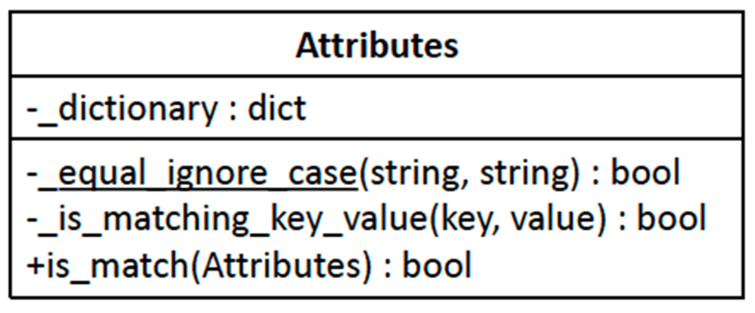
A UML class diagram for class Attributes that includes all three parts: its name, instance variables, and methods. Private method _equal_ignore_case() is underlined to indicate that it is a Class relationships determine runtime interactions
A UML class diagram that shows an application’s multiple classes and their relationships. The relationship between two classes determines how their instantiated objects can interact at run time.

A UML diagram that shows (left to right) class Catalogue, a relationship, and class Book. The dependency relationship arrow going from class Catalogue to class Book indicates that class Catalogue depends on class Book. But class Book does not depend on class Catalogue.

Diagrams that show more design detail. Class Catalogue depends on class Book via its private booklist instance variable. The multiplicity indicators show that a single (1) Catalogue object can contain zero or more (*) Book objects.

Class Catalogue has a transient dependency relationship on class Attributes, as shown by the dashed dependency arrow. The add() method of class Catalogue receives a reference to an Attributes object and the find() method is passed a reference to an Attributes object. The dependency exists only during calls to these methods.

Class Catalogue aggregates class Book. Each Catalogue object contains zero or more Book objects in a list instance variable named booklist. The open diamond at the tail of the dependency arrow is next to the diagram for the container class Catalogue.

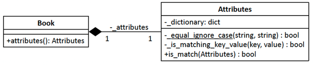
Class Book is composed of class Attributes. Each Book object has one Attributes object. According to the logic of the application, an Attributes object cannot exist without being a part of a Book object.
The difference between aggregation and composition. In this diagram, each Bookshelf object can contain 0 through 25 Book objects, and Book objects can exist outside of Bookshelf objects. Each Bookcase object is composed of 1 through 5 Bookshelf objects, but a Bookshelf object cannot exist without being a part of a Bookcase object.

Superclass Book has subclasses Fiction, Cookbook, and Howto. Also, superclass Attributes has subclasses FictionAttrs, CookbookAttrs, and HowtoAttrs. This figure shows two ways of drawing generalization diagrams.

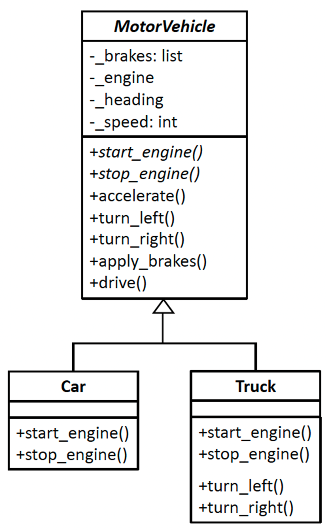
Class MotorVehicle is abstract, so its name is in a slanted font. Its methods start_engine() and shut_off_engine() are abstract, and so they are also in a slanted font. Subclasses Car and Truck must implement these abstract methods. The relationship arrow with the open triangle points to the superclass.
The label «interface» appears above the name of interface MotorVehicleInterface. All of its methods are abstract, and it contains no instance variables. The dashed relationship arrow with the open triangle indicates that subclasses Car and Truck implement the interface, and therefore, they must provide code for all the methods of the interface.

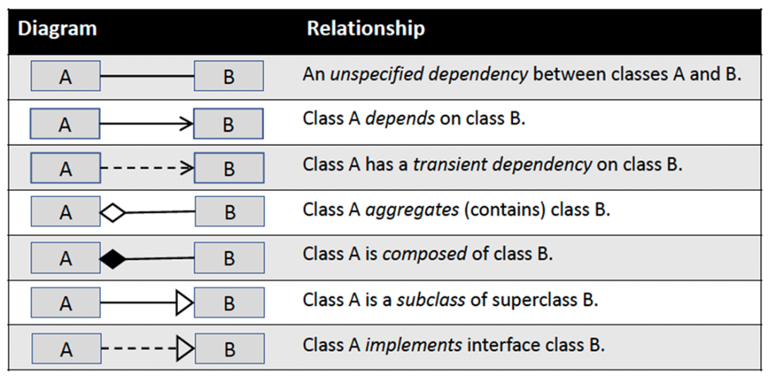
Table 4.1 Relationship lines and arrows in UML class diagrams
A UML state diagram that shows the state changes of a Car object during run time. Each box represents a state, and each arrow represents a transition from one state to another. Each transition is labeled with the behavior (event) that causes the transition. Such a diagram allows us to visualize what happens to a particular object during run time and helps to ensure that we designed the class with the correct instance variables and methods.

A state diagram for a student enrolling in a course. The filled-in diamonds are the decision branch and merge points. The heavy bars indicate where the transitions fork and join. Such a diagram would help to design a Student class with the correct instance variables and methods in a hypothetical school simulation application.

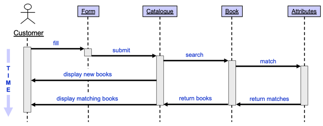
A UML sequence diagram for a customer searching for books that match target book attributes. At a high level, it shows the runtime interactions among objects involved in this use case as time goes from top to bottom. Such a diagram helps to ensure that we designed the class relationships correctly.
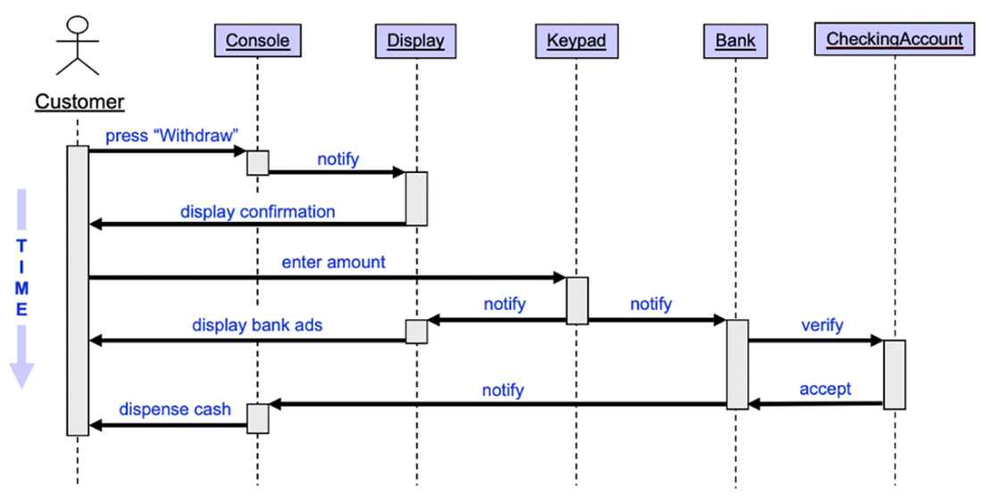
An example of a UML sequence diagram for the use case of a customer withdrawing cash from a bank ATM in a hypothetical banking application
Summary
- A project to develop an application consists of multiple activities performed in parallel by a team of developers. Design occurs throughout nearly the entire project, and mostly during the design–code–test development iterations.
- Well-designed classes are cohesive and follow the Single Responsibility Principle.
- Well-designed classes are loosely coupled and follow the Principle of Least Knowledge.
- An abstract class has at least one abstract method that its concrete subclasses must implement. It can also have instance variables and non-abstract methods.
- An interface class is an abstract class that has only abstract methods. It serves as a blueprint for all the behaviors that its concrete subclasses must implement.
- A UML class diagram provides information about an application’s classes and their relationships. Each class diagram shows the class name and, optionally its instance variables and methods. The amount of information to show depends on whether the diagram is part of a high-level or a low-level description of the application’s design.
- Different types of arrows drawn between two class diagrams indicate the relationship between the classes: dependency, aggregation, composition, or generalization.
- A UML state diagram focuses on the state changes of a single object at run time. An event causes an object to make a transition from one state to another, and the events are defined by the object’s behavior. Visualizing what happens to a particular object during run time helps to ensure that the object’s class is well-designed with correct instance variables and methods.
- A UML sequence diagram shows the high-level interactions among objects at runtime. How an object behaves during an interaction is determined by its methods. Visualizing these dynamic interactions helps to ensure that the classes are well-designed with correct methods and proper relationships.
- A design specification describes and justifies an application’s design for its current and future developers. It contains the UML class, sequence, and state diagrams. Furthermore, it can include a test plan for internal testing.
- For the verification part of software V&V, software developers perform internal testing that includes unit and regression tests during the development iterations.

 Software Design for Python Programmers ebook for free