4 The TCP/IP Networking Model
This chapter explains why networking requires more than a single technology like Ethernet and introduces layered, vendor-neutral models as the organizing framework for how data moves from one computer to another. It contrasts earlier vendor-proprietary approaches with the industry’s adoption of open standards, then positions the OSI and TCP/IP models as the core conceptual tools for understanding modern networks. Although the OSI model remains influential for terminology, the chapter focuses on the TCP/IP model as the basis of today’s Internet and as essential background knowledge for the CCNA exam.
The TCP/IP model is presented in its commonly used five-layer form: Physical, Data Link, Network, Transport, and Application. Each layer fulfills a distinct role in end-to-end communication: the Physical layer defines the medium and signaling; the Data Link layer provides hop-to-hop delivery on a local link using MAC addressing; the Network layer provides end-to-end delivery across networks using IP addressing; the Transport layer delivers data to the correct application process via port numbers; and the Application layer offers the interface and protocols (such as HTTP/HTTPS, DNS, DHCP) used by applications to communicate. The chapter clarifies the relationship to OSI (the top three OSI layers are combined into TCP/IP’s Application layer) and emphasizes key addressing behaviors, notably that destination IP addresses remain constant across the path while destination MAC addresses change at each hop.
Finally, the chapter details encapsulation and de-encapsulation, the step-by-step process by which each layer adds (and later removes) its headers—and at Layer 2, a trailer—to carry data across the network. It defines the protocol data units at each stage (segment at Layer 4, packet at Layer 3, frame at Layer 2) and the concept of payload, then shows how receivers reverse the process to deliver data to the appropriate application. It also introduces adjacent-layer interactions (each layer serving the one above it on the same device) and same-layer interactions (peer-to-peer communication between the same layer on different devices), providing a practical mental model for how layered protocols cooperate to move data reliably from source to destination.
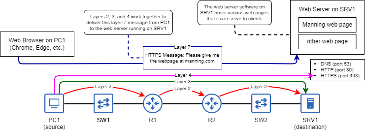
A web browser on PC1 uses a layer 7 protocol (HTTPS) to request a web page from the web server on SRV1. Layers 2, 3, and 4 work together to deliver the message to the appropriate application on SRV1. Layer 1 is the medium over which the communication occurs.
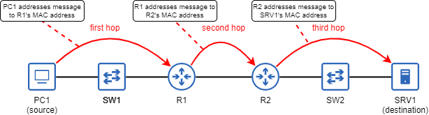
TCP/IP Layer 2. A message sent from PC1 to SRV1 takes three hops through the network: from PC1 to R1, from R1 to R2, and from R2 to SRV1. At each hop, the message is addressed to the next hop’s MAC address. A message traveling through a switch does not count as a hop.
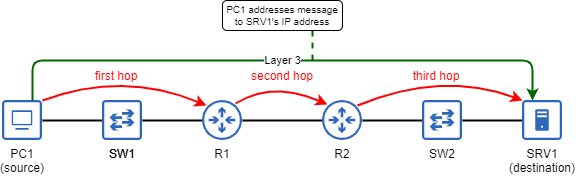
TCP/IP Layer 3. PC1 addresses a message to SRV1’s IP address. Layer 3 is responsible for the end-to-end delivery of the message, whereas Layer 2 is responsible for the hop-to-hop delivery. The destination MAC address of the message changes at each hop, but the destination IP address remains the same throughout the journey.
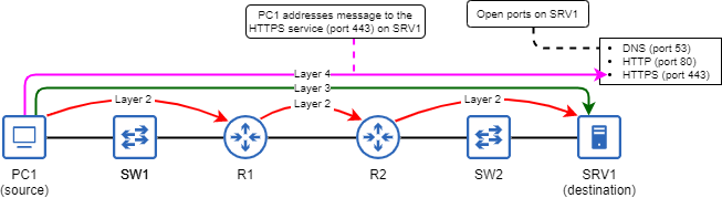
Layers 2 and 3 work together to deliver PC1’s message to SRV1. At layer 4, PC1 addresses the message to port 443, which is used by the HTTPS protocol. Three ports are open on SRV1 (53, 80, 443), meaning it will accept messages addressed to any of those ports.
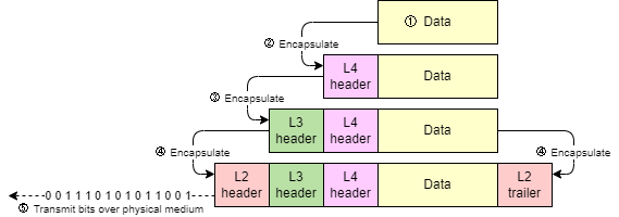
The five-step process of encapsulating and transmitting data: 1) the Application-layer protocol prepares some data, 2) layer 4 encapsulates the data with a header, 3) layer 3 encapsulates the data with a header, 4) layer 2 encapsulates the data with a header and trailer, 5) the host transmits the bits over the physical medium (ie. a UTP cable).
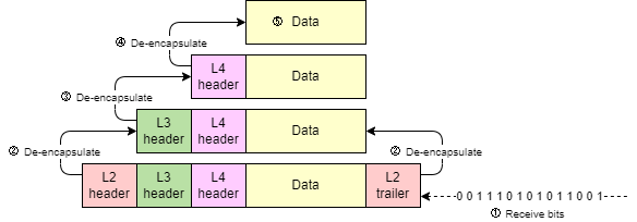
The five-step process of receiving and de-encapsulating data: 1) the destination host receives bits (the message), 2) the layer 2 header/trailer and inspected and removed, 3) the layer 3 header is inspected and removed, 4) the layer 4 header is inspected and removed, 5) the data is received and processed by the application
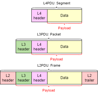
Application data encapsulated in a layer 4 header is a segment (L4PDU); a segment encapsulated in a layer 3 header is a packet (L3PDU); a packet encapsulated in a layer 2 header/trailer is a frame (L2PDU). The encapsulated contents of each PDU are that PDU’s payload.
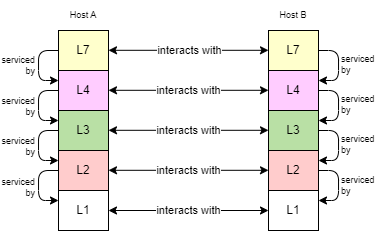
Each layer on a host provides services for the layer above it; this is called adjacent-layer interaction. When two hosts communicate, each layer on one host communicates with the same layer on the other host; this is called same-layer interaction.
Summary
- Networking models provide frameworks to define the functions necessary to enable network communications.
- Networking models are divided into layers; each layer describes a necessary function for network communications and includes multiple protocols that can fulfill the layer’s role.
- The Open Systems Interconnection Reference Model (OSI Model) is a networking model that influenced how we think and talk about networks, but is not in use today.
- The OSI Model has seven layers: 1) Physical, 2) Data Link, 3) Network, 4) Transport, 5) Session, 6) Presentation, 7) Application.
- The Internet Protocol Suite (TCP/IP Model) is the networking model used in modern networks and is named after two of its key protocols: Transmission Control Protocol (TCP) and Internet Protocol (IP).
- The original TCP/IP Model has four layers, but a more popular version has five: 1) Physical, 2) Data Link, 3) Network, 4) Transport, 5) Application (called layer 7, not layer 5).
- Layer 1 (Physical) defines physical requirements for transmitting data such as ports, connectors, cables, and how data should be encoded into electrical/light signals.
- Layer 2 (Data Link) is responsible for hop-to-hop delivery of messages. A hop is the journey from one node in the network to the next in the path to the final destination.
- Layer 2 uses Media Access Control (MAC) addresses to address messages to the next hop.
- Layer 3 (Network) is responsible for end-to-end delivery of messages, from the source host to the destination host.
- Layer 3 uses Internet Protocol (IP) addresses to address messages to the destination host.
- The destination MAC address of a message changes at each hop in the path to the destination, but the destination IP address remains the same.
- Layer 4 (Transport) is used to address messages to the appropriate application on the destination host.
- Layer 4’s addressing scheme uses port numbers (not related to physical ports). The port number identifies the layer 7 protocol being used.
- Layer 7 (Application) is the interface between applications and the network. Layer 7 protocols such as Hypertext Transfer Protocol Secure (HTTPS) are not applications themselves, but provide services for applications to enable them to communicate over the network.
- A host encapsulates application data with a layer 4 header, layer 3 header, and layer 2 header/trailer before being transmitted over the physical medium (cable or radio waves).
- After a message is received by a host, the host de-encapsulates it by inspecting and removing the layer 2 header and trailer, inspecting and removing the layer 3 header, inspecting and removing the layer 4 header, and finally processing the data in the message.
- The contents encapsulated inside of each protocol data unit (PDU) are its payload.
- The combination of data and a layer 4 header is called a segment (L4PDU).
- The combination of a segment and a layer 3 header is called a packet (L3PDU).
- The combination of a packet and a layer 2 header/trailer is called a frame (L2PDU).
- Within a computer, each layer provides a service for the layer above it; this is called adjacent-layer interaction.
- Communication between the same layer on different computers is called same-layer interaction.
FAQ
What is a networking model, and why is layering useful?
Networking models define the functions needed for devices to communicate and organize them into layers. Layering brings vendor-neutral interoperability, modular design (multiple protocols can serve a layer’s role), and clear separation of responsibilities so applications don’t need to worry about the underlying media (for example, Ethernet vs Wi‑Fi).How do the OSI and TCP/IP models relate to each other?
The OSI model has 7 layers. The commonly used 5-layer TCP/IP model combines OSI’s Application, Presentation, and Session into a single Application layer, while keeping Transport, Network, Data Link, and Physical unchanged. A 4-layer TCP/IP variant also combines Data Link and Physical into a single Link layer. We use the 5-layer model for CCNA study.Why is the TCP/IP Application layer often called “layer 7”?
Due to the influence of OSI terminology, the Application layer is commonly referred to as layer 7 even when discussing the TCP/IP model (which formally has 5 or 4 layers). This convention is widely used in networking and on the CCNA.What are the five TCP/IP layers and their core functions?
- Layer 1 Physical: Defines the physical medium and signaling (copper, fiber, radio).- Layer 2 Data Link: Formats frames and provides hop-to-hop delivery using MAC addresses.
- Layer 3 Network: Provides end-to-end delivery using IP addresses.
- Layer 4 Transport: Provides application-to-application delivery using port numbers.
- Layer 7 Application: Interface for applications to use the network (protocols like HTTP(S), DNS, DHCP).
What is the difference between hop-to-hop and end-to-end delivery?
Hop-to-hop delivery (Layer 2) moves a frame to the next device in the path using destination MAC addresses, which change at each hop. End-to-end delivery (Layer 3) addresses the final destination using an IP address, which remains the same from source to destination.Which addresses or identifiers are used at layers 2, 3, and 4?
- Layer 2: MAC addresses for hop-to-hop delivery within a LAN segment.- Layer 3: IP addresses for end-to-end delivery across networks.
- Layer 4: Port numbers to direct data to the correct application process (for example, DNS 53, HTTP 80, HTTPS 443). Note: Layer 4 port numbers are not physical connector ports.
What are encapsulation and de-encapsulation?
Encapsulation is adding protocol headers (and a Layer 2 trailer) as data moves down the stack to be transmitted: L7 data → L4 header → L3 header → L2 header + trailer → L1 bits. De-encapsulation is the reverse at the receiver: strip L2, then L3, then L4 headers and deliver the data to the application.What are segments, packets, frames, and the “payload”?
- Segment: Layer 4 PDU (L4 header + application data).- Packet: Layer 3 PDU (L3 header + segment).
- Frame: Layer 2 PDU (L2 header + packet + L2 trailer).
- Payload: The encapsulated contents inside a PDU (a frame’s payload is a packet; a packet’s payload is a segment; a segment’s payload is application data).

 Acing the CCNA Exam, Volume 1 ebook for free